Contents
- What Is a Radial Load?
- What Is an Axial Load?
- What Is a Combined Load?
- Why a Published Load Rating Is Not the Whole Answer
- Overhung Loads and Bearing Reactions
- Load Direction in Common Applications
- How Housing Style Relates to Load Direction
- A Practical Selection Process
- Information to Send with a Bearing Inquiry
- Conclusion
- Technical references
- Frequently Asked Questions
Load direction is one of the first questions to resolve when selecting a mounted bearing unit. A bearing that supports a conveyor roller may carry mainly radial load, while a bearing beside a helical gear, inclined screw, fan, or vertical shaft may also experience axial force. Many machines impose a combination of both.
Product tables commonly publish basic dynamic and static radial load ratings for the insert bearing. Those values are important, but they are not a complete statement of how much load an assembled UCP, UCF, UCFL, or UCT unit can safely carry in every direction and mounting position.
A sound selection reviews the load path through the bearing, locking system, housing, bolts, base, and machine structure—not only the bearing designation.
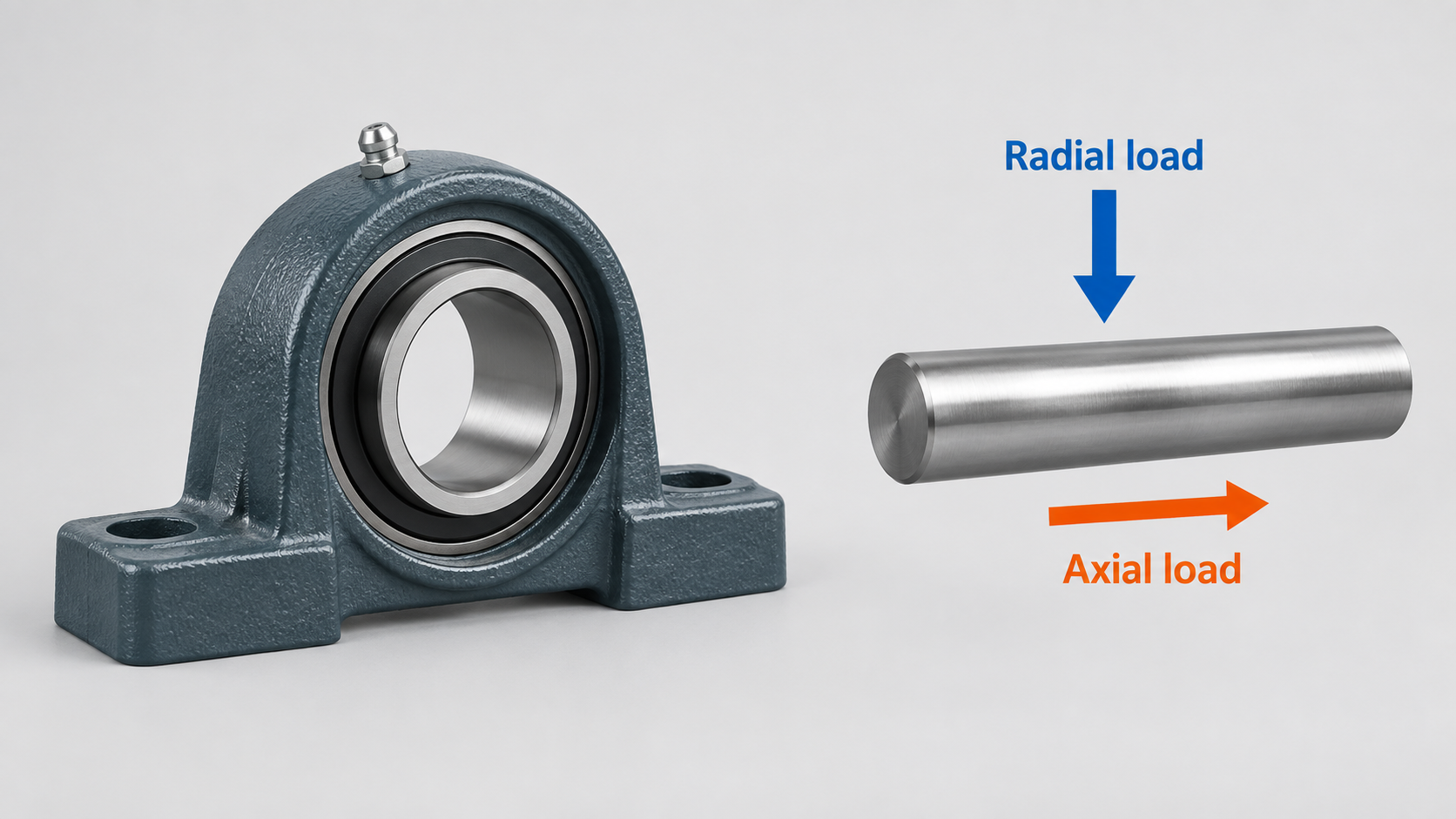
What Is a Radial Load?
A radial load acts perpendicular to the shaft centerline. Examples include the weight of a roller, belt tension on a pulley, chain pull on a sprocket, and the force created by material on a conveyor.
For an upright pillow block, a downward load toward the mounting base is a common catalog reference condition. However, actual machinery may load the housing sideways, upward, cyclically, or at an angle. Housing strength and bolt loading can change with direction, so a radial rating given for one orientation should not automatically be applied to every orientation.
Common sources of radial load
| Source of radial load |
|---|
| Belt or chain tension |
| Rotor, fan, roll, or shaft weight |
| Conveyor material load |
| Gear separation forces |
| Agricultural tool and ground reactions |
| Process pressure acting through a shaft-mounted component |
| Unbalance, impact, or shock |
Radial load at the bearing is not always equal to the external force. Its value depends on the force location, distance between supports, shaft geometry, and the reactions shared by the bearings.
What Is an Axial Load?
An axial load—also called thrust—acts parallel to the shaft centerline. It attempts to move the shaft and inner ring along the axis.
| Possible source of axial load |
|---|
| Helical gears |
| Inclined or vertical shafts |
| Screw conveyors and augers |
| Fans, impellers, and pumps |
| Thermal expansion constrained by the bearing arrangement |
| Machine adjustment or process forces |
| Assembly preload or misalignment that creates unintended thrust |
Insert ball bearings can accommodate axial load under appropriate conditions, but the allowable amount is product- and application-specific. It depends on more than the ball bearing itself.
Axial bearing capacity is not the same as axial holding power
This distinction is essential. Bearing capacity concerns the rolling contacts and the effect of combined load on bearing life or static safety. Axial holding power concerns whether the inner ring’s set screws, eccentric collar, adapter sleeve, or other locking system can keep the bearing located on the shaft.
A bearing may have enough internal capacity for a thrust component while the shaft-locking arrangement, housing, fasteners, or support structure remains the limiting part. Conversely, a strong locking system does not make the rolling bearing suitable for unlimited thrust.
Do not estimate axial capacity from the radial rating or from the number of set screws.
What Is a Combined Load?
A combined load contains radial and axial components at the same time. This is common in real machinery.
Manufacturer engineering methods convert the applied radial and axial components into an equivalent radial load for life calculation. NTN and Timken mounted-unit catalogs describe this process with product-specific factors and conditions. The calculation is not a simple addition of the two forces, and the applicable factors depend on the bearing design and the relationship between the load components.
For procurement and preliminary selection, record radial and axial loads separately. Do not combine them into one unexplained number before sending the application data to the supplier.
Why a Published Load Rating Is Not the Whole Answer
Dynamic and static ratings serve different purposes
The basic dynamic load rating is used in rating-life calculations for a rotating bearing. The basic static load rating relates to permanent deformation risk under stationary, very slow, or oscillating conditions.
Neither rating is automatically the maximum permissible load for the complete housed unit. Catalog notes may impose housing limits, shaft-fit requirements, mounting-direction limits, speed limits, or application factors.
Housing strength can be the limiting factor
The load must pass from the insert bearing into the housing and then through the mounting bolts into the machine. Cast-iron pillow blocks, flange housings, pressed-steel units, and other housing styles do not have identical strength in every direction.
When the load pulls away from a pillow-block base or acts strongly along a flange axis, confirm the housing and fastener capacity for that direction. Do not treat a bearing insert rating as a housing rating.
Shaft locking can be the limiting factor
Set-screw, eccentric-collar, and adapter-sleeve arrangements transfer force differently. Shaft diameter, tolerance, hardness, surface condition, rotation, shock, and installation torque can affect holding reliability.
For recurring movement at the shaft interface, review the common causes of pillow block bearing failure and inspect the shaft fit before assuming that higher screw torque is the correct remedy.
Mounting orientation affects the load path
A rating based on an upright pillow block loaded toward its base may not apply unchanged to an inverted unit, a vertical shaft, or a housing loaded away from its mounting surface. Confirm the permitted orientation for the exact housing.
Overhung Loads and Bearing Reactions
A pulley, sprocket, coupling, or gear placed outside the span between two bearings creates an overhung load. The farther the force is from the nearest bearing, the greater the bending moment can become.
The nearest bearing may carry a much larger reaction than a simple “total load divided by two” estimate. Shaft deflection may also increase, affecting seal contact, alignment, vibration, and fatigue.
| Information needed for an overhung load |
|---|
| Force magnitude and direction |
| Distance from the component centerline to each bearing |
| Bearing center distance |
| Shaft diameter and relevant steps |
| Component weight |
| Speed and duty cycle |
An engineering load calculation should determine the reactions at each support.
Load Direction in Common Applications
Conveyor pulleys and rollers
Belt tension and conveyed weight usually create significant radial reactions. Start-up, belt tracking, material impact, take-up force, and pulley position may change the actual load. UCT units also operate as part of a tensioning system, so adjustment force and housing position must be considered.
Fans and blowers
Rotor weight and unbalance create radial load. Air pressure, impeller geometry, or a vertical shaft can add thrust. High speed also makes balance, lubrication, fit, and alignment important.
Screw conveyors and augers
Material resistance can create both radial and axial forces. The axial component may change with feed condition, direction, blockage, and start-up. A general-purpose mounted unit should not be selected from bore size alone.
Agricultural machinery
Radial loads may vary rapidly because of soil contact, crop flow, vibration, and shock. Axial force may also arise from angled discs, helical elements, or misalignment. For more selection factors, see mounted bearing units for agricultural machinery.
How Housing Style Relates to Load Direction
Housing style is mainly selected for mounting geometry and load transfer into the machine structure.
| Housing style | Typical mounting context |
|---|---|
| UCP pillow block | Base-mounted support, commonly used with horizontal shafts |
| UCF four-bolt flange | Broad flange pattern for mounting against a machine wall or plate |
| UCFL two-bolt flange | Compact flange arrangement where space and bolt pattern differ from UCF |
| UCT take-up unit | Slides within a take-up frame to maintain belt or chain tension |
These descriptions do not establish load capacity. The exact housing, insert, fasteners, mounting direction, and manufacturer data still control the selection.
See UCF vs UCFL flange bearing units and pillow block vs flange bearing selection for mounting-style comparisons.

A Practical Selection Process
1. Draw the shaft centerline and load directions
Mark every external force and where it acts. Separate radial and axial components. Include shaft weight, pulleys, sprockets, gears, belt pull, material force, and process thrust.
2. Calculate the reaction at each bearing
Use the support spacing and load positions. Do not assume the bearings share the force equally, especially with overhung components or an asymmetrical arrangement.
3. Define the duty
Record speed, operating hours, starts and stops, reversing operation, shock, vibration, temperature, contamination, and required reliability. Peak and transient loads may matter even when average load is modest.
4. Confirm the bearing calculation
Use the exact manufacturer’s dynamic and static ratings, equivalent-load factors, life method, and application guidance. Do not combine a rating from one brand with factors or housing limits from another catalog.
5. Check every part of the load path
Review the insert bearing, locking arrangement, shaft, housing, fasteners, mounting plate, and surrounding structure. The lowest suitable limit governs the complete assembly.
6. Review alignment and thermal movement
Self-alignment does not remove the need to align bearing supports or manage shaft expansion. Read what mounted bearing self-alignment can and cannot correct.
7. Confirm lubrication and environment
Load, speed, temperature, and contamination affect lubrication requirements. Use the mounted bearing lubrication guide as a maintenance starting point, then follow the exact product and grease instructions.
Information to Send with a Bearing Inquiry
| Application information |
|---|
| Current unit designation or proposed series |
| Shaft diameter and tolerance |
| Radial load at each bearing, with direction |
| Axial load, direction, and whether it reverses |
| Load locations and bearing center distance |
| Shaft speed and operating hours |
| Shock, vibration, and start-stop conditions |
| Horizontal, vertical, inverted, or angled mounting orientation |
| Pulley, sprocket, gear, fan, or auger details |
| Temperature, moisture, dust, washdown, or corrosive exposure |
| Required life or maintenance target |
| Housing bolt pattern and available mounting space |
| Quantity, packing requirement, and destination port |
If calculated bearing reactions are not available, send a machine sketch with dimensions and force information rather than guessing.
Cixi CTZ can review UC insert bearing and mounted-unit requirements when the application data is provided. Visit the UCP series page or contact Cixi CTZ at ctz@ctz-bearing.com. WeChat: DM161116.
Conclusion
Radial load acts across a shaft, axial load acts along it, and most machines create some combination of the two. Correct mounted-bearing selection requires more than comparing a calculated force with one published radial rating.
Identify the load direction, calculate reactions at each support, account for overhung forces and transient duty, and verify the insert bearing, locking method, housing, bolts, shaft, mounting orientation, lubrication, and alignment as a complete system. Where axial load or housing orientation is significant, obtain product-specific confirmation before ordering.
Technical references
[1] NTN Bearing Units Catalog — Dynamic and Static Equivalent Radial Load. Used to cross-check equivalent-load calculation principles for mounted bearing units.
[2] Timken Housed Unit Catalog — Load Ratings and Life Calculations. Used to cross-check housed-unit load ratings and life-calculation guidance.
[3] SKF Ball Bearing Units and Insert Bearings Catalog. Used to cross-check general insert-bearing and unit selection principles.
[4] SKF Rolling Bearings — Bearing Type and Arrangement. Used to cross-check general bearing-arrangement considerations.
No universal axial-load percentage, product capacity, life result, application limit, certification, test result, search volume, or ranking guarantee has been invented.
Key Takeaways
- Radial load acts perpendicular to the shaft, while axial load acts parallel to it; many machines impose both at once.
- A published insert-bearing radial rating is not automatically the allowable load for the complete housing, locking system, bolts, shaft, and mounting direction.
- Calculate the reaction at each bearing and provide load direction, position, speed, duty, environment, shaft, housing, and mounting data for selection.
Frequently Asked Questions
What is the difference between radial and axial load on a pillow block bearing?
Radial load acts perpendicular to the shaft, while axial load acts parallel to it. A pillow block may experience both simultaneously, creating a combined load that requires product-specific calculation.
Can I use the basic dynamic radial rating as the maximum load for the complete unit?
No. The dynamic rating is used in bearing life calculations and is not automatically the maximum permissible load for the housing, locking system, bolts, shaft, or every mounting direction.
How much axial load can a UCP bearing carry?
There is no universal percentage or value for all UCP units. Axial suitability depends on the insert bearing, load ratio, speed, life requirement, locking method, shaft, housing, mounting direction, and manufacturer data.
Do two mounted bearings always share a radial load equally?
No. The reaction at each bearing depends on load position, support spacing, overhung components, shaft stiffness, and the machine arrangement. A reaction calculation is needed.
Is axial holding power the same as bearing thrust capacity?
No. Axial holding power describes how the locking system retains the inner ring on the shaft. Bearing thrust capacity concerns the rolling contacts and the effect of axial load on life and static safety. Either can limit the application.
Does self-alignment correct an unsuitable load direction?
No. Self-alignment can accommodate limited initial angular error between an insert and housing, but it does not increase housing strength, remove axial load, correct a weak mounting plate, or eliminate shaft deflection.
Need bearing units for your market?
Send us the model number, quantity, packing requirement and destination port. Our sales team will reply with a competitive quotation and delivery schedule.
Send Inquiry